Key Benefits of Engine Change-Out
- Reduce cost
- Reduce downtime
- Improve equipment reliability and lifespan
- Increase efficiency and productivity
- Improve equipment health, safety and compliance
- Enhance customer satisfaction

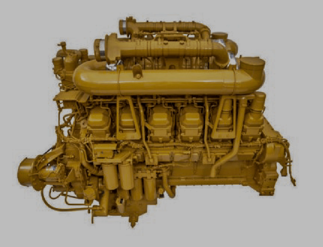
At BCMEL, an engine failure would necessitate prompt action, comprehensive diagnostics, and expert labor to effectively resolve, with safety being the top priority at all times. The engine of a Caterpillar 785 dump truck serves several critical functions essential for the operation of the drive train.

The process involves wearing personal protective equipment, inspecting tools, establishing effective communication, and conducting risk assessments. The process includes releasing air system pressure, removing the radiator, hood, air cleaners, and installing the truck body retaining cable.

Drain the oil from the torque converter. The capacity of the torque converter sump is 3.8 L (1 US gal).

Drain hydraulic oil from the 420 L (111 US gal) tank and 640 L (169 US gal) system, following the procedure outlined in the SEBU7173 Operation and Maintenance Manual.

Turn the ball valve on the fuel tank to the OFF position.

Let electricians disconnects all harness and switches,

All hydraulic, pneumatic hoses are disconnected and plug out to avoid contamination.

Main shaft is disconnected and remove all exhaust tubes ,elbows

Loosen clamp (10). Remove tube assembly (11) and tube assembly (12) as a unit.

Disconnect hose assembly (17) from the air starter.

Disconnect hose assembly (18) from the air starter and remove bolt (19) and the washer in order to disconnect the cable from the frame assembly.

Disconnect hose assembly (20) from the manifold and disconnect hose assembly (21) from the water separator and fuel filter.

Disconnect hose assembly (23) from the torque converter housing assembly

The engine can be removed by placing the air compressor aside. Do not disconnect the refrigerant hose assemblies from the refrigerant compressor. The air conditioning system must be purged and evacuated before the refrigerant hose assemblies are removed.

Disconnect three wiring harnesses that are located on the refrigerant compressor at the electrical connections. Loosen nut from the rod.

Loosen two bolts (28) and (30) in order to remove belt (29)

Disconnect cable assembly (34) from the pre-lube motor. Remove bolt (35), the washer and the clip in order to separate cable assembly (34) from the front support.

Disconnect hose assembly from the oil cooler

Place identification marks on the locations of hoses prior to removal for installation purposes. Turn two valve assemblies to the OFF position. Loosen two clamps in order to remove two hoses.

Install Tooling (B) on tube assembly. Attach a suitable lifting device to Tooling (B). Attach a lifting device to a hoist. Fasten the chain to a suitable hoist, as shown.

Position Tooling (C) under the front frame assembly, as shown. Tooling (C) will ease the removal process for tube assembly. Do not remove Tooling (C)

Attach a suitable lifting device to the front rear engine lifting eyes. Attach the lifting device to a hoist.

Remove four bolts, the washers and the nuts from cap on the right rear frame support.

Remove the engine and torque converter assembly from the truck, inspecting for any necessary components. Carefully remove the 7031 kg assembly, which weighs 15500 lb.

Get free, no-obligation quick estimate for your engineering work, please provide detailed information so we can provide you proper information for the total work and an estimate of cost! Don’t worry if you miss something on the form, we’ll work with you to get the information we need.