Key Benefits of “A”-frame change-out
- Reduce cost
- Reduce downtime
- Improve equipment reliability and lifespan
- Increase efficiency and productivity
- Improve equipment health, safety and compliance
- Enhance customer satisfaction
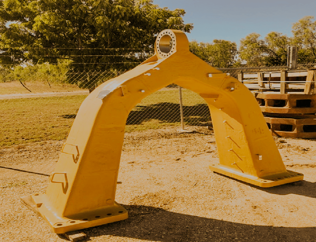
At BCMEL, The 785 A-frame change-out is a significant maintenance task involving the replacement of the A-frame assembly on Caterpillar's 785 off-highway trucks. The A-frame is a critical component that supports the front axle and suspension system. During the change-out, the truck is typically lifted and supported securely, and the old A-frame is removed, inspected, and replaced with a new one. This procedure requires specialized equipment, technical expertise, and adherence to safety protocols to ensure the truck's continued reliability and performance.

The A-frame is a large, sturdy frame structure located at the front end of the dump truck. It is typically made of heavy-duty steel to withstand the immense forces and loads encountered during operation
The A-frame serves as the primary mounting point for the dump body of the truck. The dump body, where the payload is stored, is securely attached to the A-frame using heavy-duty bolts and connections.
The A-frame facilitates the articulation of the dump body. It acts as a pivot point, allowing the dump body to tilt or raise for unloading the payload at the desired location. This articulation mechanism is crucial for efficient dumping operations
The A-frame integrates with the dump truck’s hydraulic system. Hydraulic cylinders are mounted on the A-frame, and they extend and retract to control the movement of the dump body. These cylinders provide the necessary force to raise, lower, and tilt the dump body as required
Control linkages, such as rods and cables, are connected to the A-frame. These linkages transmit control inputs from the driver’s cab to the hydraulic system, allowing the operator to manipulate the dump body’s movement with precision
The design of the A-frame incorporates safety features to ensure stable and secure operation of the dump truck. It helps distribute the load evenly, minimizing the risk of tipping or instability, especially when the dump body is fully loaded and raised
The A-frame design may include features to facilitate maintenance and servicing of the dump truck. Access panels or openings may be provided for easy inspection and maintenance of hydraulic components and connections
All personal protective equipment is worn and tools inspected, effective communication is established and risk assessment done to mitigate the risk that exist in the process

Before installation, ensure components are clean and free of foreign material. Inspect O-ring seals for wear and replace if needed. Use nitrogen liquid or press for installation.

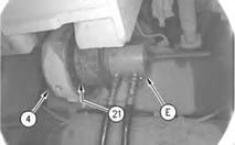
Use Tooling (E) in order to install bearing (21) into rear axle housing (4)
Position plates (20) onto rear axle housing (4). Install bolts (19). Tighten bolts (19) to a torque of 270 ± 25 N·m (199 ± 18 lb ft).
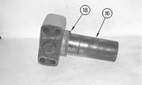
Install washer (18) and cap assembly onto pin (16)

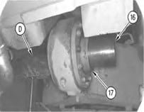
Use Tooling (D) in order to position pin (16) and the cap assembly into rear axle housing (4). The weight of pin (16) is approximately75 kg (166 lb)

Install ring (17) onto pin (16)

Use Tooling (D) in order to position pin (16) and the cap assembly into rear axle housing (4). The weight of pin (16) is approximately75 kg (166 lb).
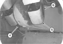
Install ring (17) onto pin (16).
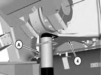
Install bearing cap (15) onto pin (16), as shown
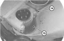
Use Tooling (A) in order to lower the frame assembly and raise rear axle housing (4) by approximately 75 mm (3 inch) in order to connect rear axle housing (4) to the frame assembly

Use Tooling (B) to install bolts and connect bearing cap to frame assembly, tighten to 500 ± 50 N·m, turn by 60 ± 5 degrees, and apply Tooling (G) to bolts.

Repeat Steps 9 for the remaining bearing cap

13. Install plate (13). Install three of bolts (12), equally spaced. Tighten bolts (12) to a torque of 200 ± 25 N·m (148 ± 18 lb ft). Use Tooling (F) in order to measure the distance between the pin and the outside surface of plate (13).

Remove bolts (12) and plate (13).

Measure the thickness of plate (13) and subtract this value from the value that was obtained in Step 11.

Install a number of shims that equals the value that was obtained in Step 15 plus 0.25 mm (0.01 inch). Install plate (13). Install bolts (12). Tighten bolts (12) to a torque of 750 ± 90 N·m (555 ± 66 lb ft)

Use a suitable lifting device in order to position drive shaft (11). Install new bolts (10). Tighten bolts (10) to a torque of 550 ± 20 N·m (406 ± 15 lb ft).

Connect hose assembly (5) to rear axle housing (4)

Position hose assembly (2) and install bolts.

Connect hose assembly (2) to magnetic screen (1)

Refill the transmission tank with hydraulic oil. Refer to Operation and Maintenance Procedure, "Transmission Tank Oil - Change".

Install the hoist control valve. Refer to Disassembly and Assembly, "Control Valve (Hoist) - Remove ".

Remove the wheel chocks. Refer to Disassembly and Assembly, "Wheel Chock (Front and Rear) - Remove and Install

Get free, no-obligation quick estimate for your engineering work, please provide detailed information so we can provide you proper information for the total work and an estimate of cost! Don’t worry if you miss something on the form, we’ll work with you to get the information we need.